Posts

Showing posts with the label Project Structure

UR10e control architecture
Image
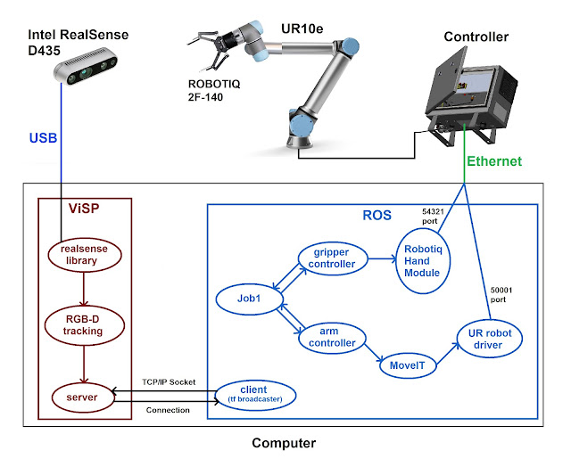
Now that I am able to control the arm of the robot as well as the gripper, it is now time to create an interface that can be used to control both the arm and the gripper.  This interface should be completely agnostic to any use case that is being developed. Since gripper control and arm control are two independent procedures that can be running simultaneously, this interface should put these two controllers at the same level. Following this philosophy, any job that I want to develop in the future will be able to call any one of these controllers by the same method! Here we can see the structure of the first complete job.  In this case, an object that is continuously being tracked through a RGB-D camera is followed by the robot arm and then is picked up and stored in a box.  As we can see, both controllers (arm and gripper) are at the same level, and the job1 ROS node is communicating with both of them simultaneously. The gripper controller is described in this previous p...

Real-time UR10e following a tracked object

Image
For a first trial, it was developed this demonstration of a real-time followed object that is being tracked using one RGB-D camera (Intel RealSense D435).   As seen in this previous post , ViSP is used to process the images acquired by the RealSense RGB-D camera and to continuously track the object . A TCP/IP Socket Connection is established (inside the same computer) between ViSP and ROS . This socket communication is responsible for bringing the geometric transformation between the camera and the object to the ROS environment. This previous post describes with more detailed information this connection. Besides the transformation between the camera and the object, it is also required to know the transformation between the robot and the camera . For the robot to understand the position and orientation of the object in reference to the robot himself, this transformation becomes crucial. For getting it, I performed a manual calibration , as described in this previous post . Fina...

TCP/IP connection: UR10e - External PC

Image
To use any of the features that have been published on my recent posts (UR10e external control, gripper external control, etc), it is required to have the cobot connected to my external computer.  For that an Ethernet cable is connected from the UR10e controller to my PC, using a TCP/IP communication protocol.  For enabling that communication, On UR10e Teach Pendant : Click on Menu (top right corner) + System + Network Configure: Network method : Static Address IP address: 192.168.56.2 Subnet mask: 255.255.255.0 Default gateway: 192.168.56.2   Click on Apply   Disable EtherNet/IP fieldbus: Installation > Fieldbus > EtherNet/IP > Disable   On External Computer :       After you connect the cable, you need to configure the IPv4 like this:

Socket connection between ViSP_WS and ROS

Image
To avoid the problem described in my last post, and to use ROS to control the robot, it's now time to connect the ViSP as a standalone system with ROS. For that we came out with the idea of creating a TCP/IP socket connection between these two systems. This solution will ensure the robustness of the RGB-D tracking that we have already seen here.    This diagram symbolizes the connection structure and the tasks that each part is responsible for.  It is important to notice that the server will only send the pose information when a request is made by the client. This means that there will be some time delay between the real woodblock pose and the pose that is being published in ROS environment (even being the slightest lag).    

Project Structure - main architecture

Image
Contextualization This project aims to relieve human operators of repetitive work that causes multiple back injuries for the workers, by replacing one person for a collaborative robot. At the moment, the task in hand requires two human operators to: lift a relatively large board (one person on each side)  Check that side of the board Turn the board around Check that other side of the board If both sides are approved, place the board on the automatic treadmill For this, it will be developed a ROS based project, working with a Universal Robot 10 e-series. The workflow of this project is detailed right below. Structure For future development purposes, this task will be built in a modular way, where each step can occur independently of the other steps. This way, it will be possible to start from a simple and fully working job and only then develop and implement more advanced tools that will contribute for the robustness of the project.  The proposed workflow main structu...